Mittelspannungsnetz 20 kV
The distribution system operator's grid to which the installation is connected. Its short-circuit power at the connection point determines how strongly the installation reacts on the grid and how the protection must be rated.
For a battery storage unit the medium-voltage level is the normal case: low voltage cannot carry the connected load, high voltage makes the connection disproportionately expensive.
Netzverknüpfungspunkt
Governed by VDE-AR-N 4110
The point at which the customer installation is connected to the grid. It defines the connected load that is permitted, and it is where all requirements of the connection rule apply — not the individual device behind it.
It is set by the network operator in the grid connection commitment. Behaviour at this point is governed by VDE-AR-N 4110.1
Übergabestation Schaltanlage und Messung
Governed by DIN EN IEC 62271-200
The building at the grid connection point where grid and customer installation meet. It houses the panels for the incoming grid cable, the transfer panel with circuit breaker and protection, the billing metering and the telecontrol equipment.
Design, access and equipment are specified by the network operator — it must be able to enter the station at any time. The switchgear itself is metal-enclosed switchgear to DIN EN IEC 62271-200.
Trennschalter sichtbare Trennstelle
Provides a visible, secured isolating point so that work on the installation is permitted. It does not switch under load: the circuit breaker opens first, the disconnector second.
Together with the earthing switch it is the basis of the five safety rules — isolate, secure against reclosing, verify absence of voltage, earth and short-circuit, cover adjacent live parts.
Abrechnungsmessung Wandlermessung, RLM
Governed by MsbG
Meters feed-in and off-take separately by direction — a storage unit does both, and each is settled differently. At medium voltage the measurement is taken via current and voltage transformers as registering load metering in quarter-hour values.
The metering point operator is responsible under the German Metering Point Operation Act. Whether metering sits on the medium- or low-voltage side is decided by the network operator; behind the transformer its losses are accounted for arithmetically.
Leistungsschalter Übergabeschalter
Governed by DIN EN 62271-100
The only switching device in the chain that can handle short-circuit current and disconnect the installation in the event of a fault. Where a protection device operates a switching device, the connection rule requires a circuit breaker — a switch-disconnector is not sufficient.
It is tripped by the network and system protection and by the short-circuit protection. Rating and testing to DIN EN 62271-100.
Netz- und Anlagenschutz NA-Schutz
Governed by VDE-AR-N 4110
Monitors voltage and frequency at the grid connection point and disconnects the installation as soon as the grid leaves the permitted limits. Above all it prevents one thing: the installation continuing to energise a grid that has been switched off, endangering line workers.
It does not sit in the line but measures via transformers and acts on the circuit breaker — which is why it is drawn beside it, not within it. Which protection functions are required is set by VDE-AR-N 4110, the actual values by the network operator; the settings are secured against alteration.1
Fernwirktechnik Anbindung Netzleitstelle
Governed by VDE-AR-N 4110
Connects the installation to the network operator's control centre. Setpoints for active and reactive power arrive from there, as does the instruction to curtail feed-in when required; measurements, switch positions and fault signals go back.
VDE-AR-N 4110 requires this remote controllability as a precondition of connection.1 Transmission path and protocol are specified by the network operator; IEC 60870-5-104 over a dedicated link separated from the internet is common.
Eigentumsgrenze Netz / Kundenanlage
From here the installation belongs to the connecting party. The boundary determines who builds, tests, operates and maintains which part — and it does not necessarily sit where the metering sits.
Its exact location is set out in the grid connection contract. This line is not a component but a boundary of responsibility.
Transformator 20 / 0,8 kV
Governed by DIN EN 60076
Steps the medium voltage down to the inverter voltage, which for battery storage is usually between 600 and 800 volts. Its rated power, together with the grid connection, limits what the installation can actually do.
It also provides galvanic separation: the vector group — for storage at the medium-voltage grid usually Dyn — helps determine how the installation behaves under unbalanced faults and how the star point on the low-voltage side is treated. Rating and testing to DIN EN 60076.
Niederspannungs-Hauptverteilung NSHV
Governed by DIN EN 61439
The busbar carrying the inverters, the auxiliary supply and the ancillary systems. It holds the outgoing switches and short-circuit protection for each string so that a fault in one outgoing circuit does not shut down the whole installation.
It is a switchgear assembly and is built, rated and verified as such to DIN EN 61439 — including proof of internal arc withstand where that is required.
Eigenbedarf Steuerung, Licht, USV
Governed by DIN VDE 0100
Supplies everything the installation needs for itself: control, protection devices, lighting, communication. It is fed from the low-voltage main distribution board and additionally backed up without interruption so that protection, signalling and communication keep working during a grid outage.
Installed to DIN VDE 0100. Its consumption reduces the efficiency of the installation and therefore belongs in the revenue calculation, not only in the electrical design.
Thermomanagement Kühlung des Containers
Keeps the cells in the temperature window in which they may operate: too warm ages them faster, too cold limits the available power. In large storage units the cooling is usually liquid-based and part of the container.
It has no connection standard of its own. Its power demand belongs in the sizing of the auxiliary supply — and in the efficiency calculation, because it is largest in summer, when revenues are largest too.
Brandmeldeanlage Gas- und Rauchdetektion
Governed by DIN 14675
Detects gas, smoke or a rise in temperature inside the container and signals a permanently staffed location. With lithium-ion cells the point is to detect thermal runaway early: cells release gas before smoke becomes visible, which is why gas is the detection criterion.
Structure and operation to DIN 14675, the system technology to DIN VDE 0833-2. What happens in the event of a fire is agreed between operator, insurer and the local fire brigade in the fire safety concept.
Anlagenregler EZA-Regler
Governed by VDE-AR-N 4110
Translates the control centre's requirements into setpoints for the individual inverters. What matters is that it controls at the grid connection point, not at the individual device — what is required is the behaviour of the installation as a whole.
Without it, active power setpoints and reactive power characteristics could not be met as soon as more than one inverter is involved. Its behaviour is part of the plant certificate under VDE-AR-N 4110.1
Wechselrichter PCS, bidirektional
Governed by VDE-AR-N 4110
Converts between the battery's direct current and the grid's three-phase current, in both directions — hence power conversion system rather than inverter in the narrow sense. In a real installation several units work in parallel onto the same busbar.
It produces the grid behaviour the connection rule requires: active power control, reactive power provision, behaviour during voltage dips. The unit certificate proves that it can — without that certificate the unit cannot be used for a connection under VDE-AR-N 4110.1
DC-Sammelschiene Stränge und Trenneinrichtungen
Connects the battery strings to the inverter. Each string has its own isolating and protective device so that individual racks can be de-energised without shutting down the installation — in operation that is the difference between maintenance and downtime.
There is no dedicated standard for the direct-current side of a battery storage unit. What applies are the cell manufacturer's specifications and the safety concept of the installation.
Batteriecontainer Racks, BMS, Löschanlage
Governed by DIN EN IEC 62933-5-2
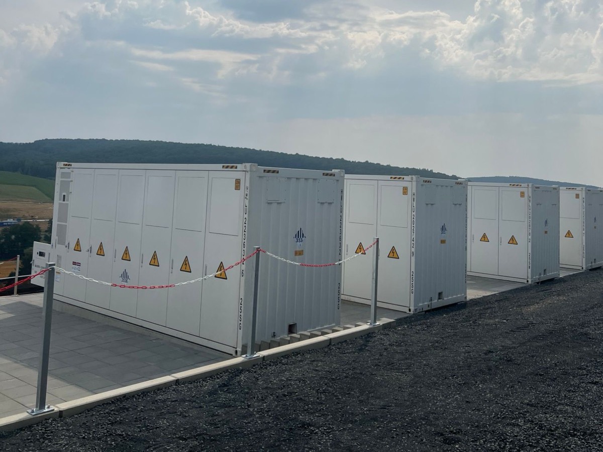
Houses the battery racks with the cells, the battery management, the cooling and the fire suppression. The battery management monitors cell voltages and temperatures and disconnects the strings via the main contactors as soon as limits are exceeded.
Safety requirements for grid-connected storage are set by DIN EN IEC 62933-5-2 (VDE 0520-933-5-2). It covers the entire life cycle, from design to end-of-life management.